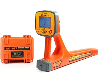
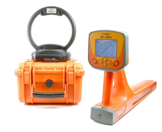
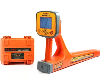
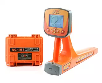
Cable and pipe locator Success AG-319G


Success AG-319G - underground GPS cable and pipe locator
 Energized
cables
 Non
Nonenergized
cables
 Armored
fiber
optic
cables
 Metal
Metalpipelines
Success AG-319G - underground GPS cable and pipe locator
The set for fast and accurate inspection of buried utilities (metal pipelines, cable lines) including a powerful transmitter for more effective tracing on longer distances.
Key features
- Indication of utility direction on the screen.
- Automatic measurement of utility depth and current of the cable.
- The set includes a transmitter with high electric power up to 270 W for tracing up to 10 km.
 LCD
LCDscreen
 Utility
detection
depth
 Tracing
distance
 Utility
position
indication
 GPS/
GPS/GLONASS
optional
Description of cable and pipe locator Success AG-319G
The set for inspection of buried utilities (cable lines, metal pipelines, and other utilities made of conductive materials).
The set includes a monoblock receiver with a large LCD screen, which indicates actual position of cable and pipe and automatically measures burial depth up to 10 m, as well as current rate.
Built-in GPS/GLONASS module to store the coordinates of located utility.
"Probe" mode for locating NON-METALLIC utilities with pipe sonde (optional).
The most powerful multi-frequency transmitter with a range up to 10 km.
Contact and non-contact connection to utility.
Application of cable and pipe locator Success AG-319G
- Detection of cables and any metal pipelines underground up to 10 m.
- Direct digital measurement of the depth up to 10 m.
- Tracing of underground utilities at distance up to 10 km.
- Detection of energized cables.
- Detection of intersections of the pipeline and cable.
- Detection of defects in cable lines.
- Survey the ground before the excavation works.
- Storing of GPS\GLONASS coordinates and mapping of located utilities.
- Location of non-metallic utilities with optional pushing rod and pipe sonde.
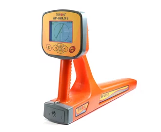
Features of AP-019.3 receiver
- Advanced digital monoblock receiver AP-019.3.
- Indication of utility on the screen.
- Automatic measurement of burial depth and current rate.
- Built-in GPS/GLONASS module to store the coordinates of located utility.
- "Probe" mode for locating NON-METALLIC utilities with pushing rod and pipe sonde (optional).
- Several indication modes: "Route", "Graph", "Graph+", "MIN&MAX", "R.dis." (Relative distance to the utility) and "2 frequencies" which allow operator to utilize full potential of device.
- Additional functions when connecting external sensors.
- Vast range of supported frequencies (50(60) / 100 (120) / 512 / 1024 / 8192 / 32768 Hz, WideBand 40…8000 Hz, Radio 8…40 kHz).
- Menu in English and Russian.
- Connect Power Bank and work at sub-zero temperatures, Power Bank is hidden under the clothes of the operator.
Features of AG-120 transmitter
- Automatic matching by a given current in the load, instead of the output power, allows you to get a predictable signal level at the input of the search receiver.
- The multi-frequency (200...10000 Hz) multifunctional device can be equipped with any receiver that uses this frequency range.
- Automatic selection of output power by a program.
- Built-in "output multimeter" indicates voltage, current, resistance and power in the load.
- High output current (up to 15A) allows efficient operation on "low impedance" (up to short-circuit) loads (e.g. grounded pipes).
- High output voltage (220 V off-line / 330 V with optional battery) allows efficient tracing "high resistance" utilities of long distances.
- Multifunctionality: operation without direct connection with resonant transmitting antenna, inductive clamps, impact mechanism and insulation control sensor.
- Working in rainy weather (on/off; view parameters with the lid closed).
Functional features of AP-019.3 in different operation modes
"Route" mode
"Route" mode screen is considered to be main. Utility axis position, burial depth and current of the utility are indicated on LCD screen. Detection of utility is performed in semi-automatic mode clearly and quickly.

"Graph" mode
Moving graph of signal strength level at the selected frequency is indicated together with utility position. "Graph" mode is used when the signal is too low or when the electromagnetic field is distorted.

"Graph+" mode
This mode provides the location of energized power cables which cross another located utility.

"MIN&MAX" mode
The "MIN&MAX" mode on the graphs of signal level changes helps to locate the center of a cable or pipe more accurately. Also it helps indicating several utilities laying nearby.

"R.dis." modes (Relative distance to the utility)
These modes are used when cables and pipes are positioned close to each other to measure burial depth of located utilities.


"2 frequencies" mode
In the "2 frequencies mode", the cable condition and pipeline protection diagnostic is performed using the transmitter.

Linking utilities to a terrain map using the GPS/GLONASS module
Using the built-in GPS/GLONASS module, the current coordinates of the receiver are detected. By pressing a key on the control panel, the date, time, current coordinates and measured parameters of the main points are stored in the receiver’s RAM: the burial depth and current rate.

The saved data are uploaded to PC for mapping and further processing: editing the connection between points (track construction), saving the track to a database, as well as to a KML or CSV file.
MapProgram
This program is designed for reading of saved points from the AP-019.3 device, displaying locations on Google Maps and Yandex Maps, editing of interrelation between points (construction of a track), saving a track to a database, as well as to KML-file and CSV-file. All points are stored in database. The database is stored in the folder with exe file. The name of the database is "GPSdb".
To work with the data saved in the receiver AP-019.3 the device is connected to a computer using a USB cable.
System requirements for the computer
- Operating system: Windows XP 32/64 Bit, Windows 8.1 32/64 Bit, Windows 8 32/64 Bit, Windows 7 32/64 Bit, Windows Vista 32/64 Bit, Windows 10 32/64 Bit.
- Processor: Pentium 4 1.5 GHz or Athlon XP 1500+ processor or higher.
- RAM: 1 GB GAM.
- Hard drive space: 300 MB of free space.
MapProgram window

All the information about the program is contained in the "Help" section.
UtilityLoc program
The UtilityLoc program is designed for the AP-019.3 receiver and has greater functionality for saving data in publicly available formats than the MapProgram. Users have access to its updates for the duration of its use.
System requirements for the computer
- Operating system: Windows XP 32/64 Bit, Windows 8.1 32/64 Bit, Windows 8 32/64 Bit, Windows 7 32/64 Bit, Windows Vista 32/64 Bit, Windows 10 32/64 Bit.
- Processor: Pentium 4 1.5 GHz or Athlon XP 1500+ processor or higher.
- RAM: 1 GB GAM.
- Hard drive space: 300 MB of free space.
The disc comes with a key to activate the software.
For information on the cost of the program and its license, please contact our managers.
AP-019.3 operation for utilities tracing
During the operation there will be the following indication on the screen:

- There is indication in the form of point on the screen, it means the utility is far away from the operator. It’s necessary to move towards the point.
- The utility axis is appeared on the screen and its position relative to the operator.
- The axis in the middle shows that the operator is above the utility. There is automatically calculation of the depth and current.
Cable and pipe locator Success AG-319G is recommended for application in the following industries
- Power.
- Public utilities.
- Heat and water supply.
- Oil and gas industry.
- Geodesy.
Specifications of AP-019.3 receiver
| Parameter | Value |
|---|---|
| Receiver Quasi resonant filter centre frequency | 50(60) / 100(120) / 512 / 1024 / 8192 / 32768 Hz |
| “Wide band” frequency band | 0,04...8 kHz |
| Frequency range "Radio" | 8...40 kHz |
| Sonde frequency | 512 Hz |
| Dynamic range of incoming signal | 120 dB |
| Number of embedded sensors | 4 |
| Max. sensitivity (in "Graph" mode: F0 = incoherent distortion +10 dB is 31…35 kHz) | 5 mkA at 1m distance |
| Data log capacity | 2300 "points" |
| Connected external sensors | CI-105, HP-117, DODK-117, DKI-117 (made by "TECHNO-AC") |
| Sensitivity control | - Auto-for 2D display "Route"; - Semi-automatic or manual (optional) - for the "Graphic", "Graphic+", MIN&MAX and "Sonde"; - Automatic or manual (optional) - for the "2F" mode |
| Determination the burial depth of the route | - Automatically in "Route" mode 0...10 m; - By pressing a button in "Sonde" mode |
| Burial depth identification accuracy | ±5% |
| Identification of the effective current in the route | Automatically in "Route" mode 0.001...49.99 A |
| Accuracy of current measurement of received signal | ±5% |
| Support of energy saving (intermittent) modes of the route locating transmitters | At combined work with the route locating transmitters made by "TECHNO-AC" ("Pulse" mode) |
| Visual indication | Graphic display LCD display, 320x240 pix., with LED backlight |
| Induced parameters | - 2D visualization of the route location relative to the device; - Graphics of the signal level from sensors; - Route burial depth; - Signal current; - Signal strength; - Settings and control parameters |
| Audio indication | Built-in speaker: - natural filtered sound; - buttons sound indication |
| Power source | - 4...7 V (4 type C batteries); - External Power Bank – optional |
| Time of continuous operation from the single battery set | Not less than 20 hours |
| Automatic shutdown when the device is not active | After 30 minutes of inactivity |
| Operating /storage temperature range | -20...60°С / -30...60°С |
| Dust and water protection degree | IP54 |
| Dimensions | 330x140x700 mm |
| Weight (excluding batteries) | 2,4 kg |
Specifications of AG-120 transmitter
| Parameter | Value |
|---|---|
| Frequency of generated signal | |
| Frequencies f1, f2, f3 (three frequencies fixed in memory), Hz | Range 200…9999 (selected in the range with a resolution of 1 Hz and accuracy of ±0,05% Hz and input in the power-independent memory) |
| Frequency f4 (one "temporary"), Hz | Range 200…9999 (selected instead of one of the "fixed", not input to the memory, exists while the power is on) |
| Output parameters | |
| Output current | |
| Maximum in manual mode: | |
| - continuous and two frequencies generation, А | 10 |
| - pulse generation, А | 15 |
| Maximum output voltage: | |
| - when working in safe mode, V | 24 |
| - under internal power supply, V | 220 (170 when "2F") |
| - with added external accumulator 12 V, V | 330 (260 when "2F") |
| - when supplied from power adapter, V | 140 (110 when "2F") |
| Maximum output power when accumulators are fully charged: | |
| - under internal power supply or from external accumulator 24 V, W | 120 continuous at a load of 1,2…300 Ohm / 180 pulsed at a load of 0,8…200 Ohm |
| - with added external accumulator 12 V, W | 180 continuous at a load of 1,8…450 Ohm / 270 pulsed at a load of 1,2…300 Ohm |
| - from power adapter, W | 70 at a load of 0,7…200 Ohm |
| NOTE. When incompletely charged or (and) frequencies above the "logarithmic middle point" of the range (1,4 kHz) the reduction of the maximum power with an increase of frequency and load resistance is possible at no more than 3 dB. | |
| Resistance range for matched loads, broader than | |
| For minimum specified current (0,1 А): | |
| - for internal power, Ohm | 4…2200 (4…1700 when "2F") |
| - with external accumulator 12 V added, Ohm | 4…3300 (4…2600 when "2F") |
| For maximum continuous current (10 А): | |
| - for internal power, Ohm | 0…1,2 |
| - with external accumulator 12 V added, Ohm | 0…1,8 |
| For maximum pulsed current (15 А): | |
| - for internal power, Ohm | 0…0,8 |
| - with external accumulator 12 V added, Ohm | 0…1,2 |
| Matching with the load | - automatic, providing achieving of the specified current in the load; - manual (buttons « » or « ») |
| Design parameters | |
| Output power amplifier | Pulsed, technology CLASS D(BD); Efficiency factor > 80% |
| LED-based superbright digital indicators of high temperature range | - all supply voltages; - modes and settings; - power resource; - OUTPUT MULTIMETER: "output voltage", "current in load", "load resistance", "power in load" |
| Control | Nine-button keyboard and external power switch with generation indicator providing work under rain with closed cover (due to parameter setup "memorizing"), intuitive interface |
| Dimensions of electronic block (case), maximum, mm | 305х270х194 |
| Weight of electronic block, maximum, kg | 12 |
| Operating temperature range, °С | -30…+50 |
Basic set
| № | Name | Quantity |
|---|---|---|
| 1 | Receiver АP-019.3 | 1 pcs. |
| 2 | Transmitter АG-120 | 1 pcs. |
| 3 | Inductive antenna IEM-301.3 | 1 pcs. |
| 4 | Contact magnetic AG120.02.090 | 2 pcs. |
| 5 | Grounding rod AG110.02.004 | 2 pcs. |
| 6 | Operation manual | 1 pcs. |
Video

AP-19.1 & AP-19.3 cable location receiver detailed manual
The Modern digital device in monoblock body with a large LCD display.

Review of transmitter AG-120
The transmitter AG-120 is an automatic utility locating transmitter designed for the generation of the propagating electric oscillations in the traces of the buried utilities using electromagnetic method of the trace search.
Accessories

Appliable with transmitters AG-105, AG-107, AG-120 and AG-144.1.

Appliable with transmitters AG-105, AG-107, AG-120 and AG-144.1.

Appliable with transmitters AG-105, AG-107, AG-120 and AG-144.1.

Compatible with the receivers АP-019, AP-027.

Compatible with the receivers АP-019, AP-027.

Compatible with the receivers АP-019 and AP-027.
Sensor is used for precise location of a single cable in a bunch of other cables.

Compatible with the receivers AP-019 and AP-027.
It is used for the selection of the cable from a bunch, for location of internal wiring and cable fault location.

Extra grounding wire and rod for better quality of underground utility location.

Set of type C rechargeable accumulators and charger for AP-019 and AG-105.

Compatible with the receiver AP-019.3.
Compatible with the receiver AP-019.3.