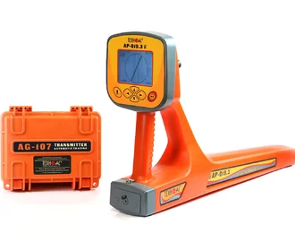
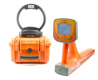
Cable and pipe locator Success AG-309.15N


Success AG-309.15N - underground cable and metal pipe locator
 Energized
cables
 Non
Nonenergized
cables
 Armored
fiber
optic
cables
 Metal
Metalpipelines
Success AG-309.15N - underground cable and metal pipe locator
The set for fast and accurate location of underground utilities and their depth measurement.
Key features
- Indication of utility position on the screen.
- Automatic measurement of utility depth and current rate of the cable.
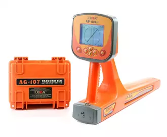
- The set includes an autonomous transmitter AG-105 with electrical power up to 20 W and built-in inductive antenna for tracing up to 3 km.
 LCD
LCDscreen
 Utility
detection
depth
 Tracing
distance
 Utility
position
indication
Description of cable and pipe locator Success AG-309.15N
The set is designed for accurate location of underground utilities and their depth measurement (power/signal cable lines, armored fiber optic cables, pipes made of conductive materials), search for faults of cable lines, allows in the shortest time and with great reliability to survey the ground before the excavation works and prevent damage to engineering utilities.
The set includes a monoblock receiver with a large LCD screen, which indicates actual position of cable and pipe and automatically measures burial depth of located utility up to 10 m, as well as current rate.
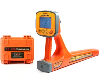
Autonomous transmitter with LCD display and built-in induction antenna. This model is equipped with 20 W transmitter and allows to trace underground cables and pipes up to 3 kilometers.
Contact and non-contact connection to utility.
Application of cable and pipe locator Success AG-309.15N
- Detection of cables and any metal pipelines underground up to 10 m.
- Direct digital measurement of the depth up to 10 m.
- Tracing of utilities at distance up to 3 km.
- Detection of energized cables.
- Search for intersections of the pipeline and cable.
- Detection of defects in cable lines.
- Survey the ground before the excavation works.
Features of AP-019.1 receiver
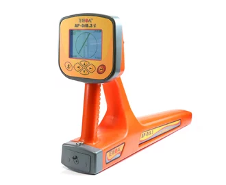
- Advanced digital monoblock receiver AP-019.1.
- Indication of utility on the screen.
- Automatic measurement of burial depth and current rate.
- Several indication modes: "Route", "Graph", "Graph+", "MIN&MAX", "R.dis." (Relative distance to the utility) and "2 frequencies" which allow operator to utilize full potential of device.
- Additional functions when connecting external sensors.
- Vast range of supported frequencies (50(60) / 100 (120) / 512 / 1024 / 8192 / 32768 Hz, WideBand 40…8000 Hz, Radio 8…40 kHz).
- Menu in English and Russian.
Features of AG-105 transmitter
- Built-in "multimeter" indicates the operator's choice of voltage, current, resistance, output power or supply voltage.
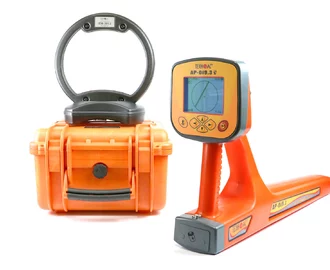
- Built-in transmitting antenna for non-contact pointing of the signal to utility.
- Manual power reduction/increase after auto-adjustment.
- Small size and weight.
Functional features of AP-019.1 in different operation modes
"Route" mode
"Route" mode screen is considered to be main. Utility axis position, burial depth and current of the utility are indicated on LCD screen. Detection of utility is performed in semi-automatic mode clearly and quickly.

"Graph" mode
Moving graph of signal strength level at the selected frequency is indicated together with utility position. "Graph" mode is used when the signal is too low or when the electromagnetic field is distorted.

"Graph+" mode
This mode provides the location of energized power cables which cross another located utility.

"MIN&MAX" mode
The "MIN&MAX" mode on the graphs of signal level changes helps to locate the center of a cable or pipe more accurately. Also it helps indicating several utilities laying nearby.

"R.dis." modes (Relative distance to the utility)
These modes are used when cables and pipes are positioned close to each other to measure burial depth of located utilities.


"2 frequencies" mode
In the "2 frequencies mode", the cable condition and pipeline protection diagnostic is performed using the transmitter.

AP-019.1 operation for utilities tracing
During the operation there will be the following indication on the screen:

- There is indication in the form of point on the screen, it means the utility is far away from the operator. It’s necessary to move towards the point.
- The utility axis is appeared on the screen and its position relative to the operator.
- The axis in the middle shows that the operator is above the utility. There is automatically calculation of the depth and current.
Tracing metal pipelines transmitter AG-105
Tracing metal pipelines on the distance up to 3 km using transmitter.

Cable and pipe locator Success AG-309.15N is recommended for application in the following industries
- Power.
- Telecommunication.
- Construction.
- Public utilities.
- Heat and water supply.
- Oil and gas industry.
- Geodesy.
Specifications of AP-019.1 receiver
| Parameter | Value |
|---|---|
| Receiver filter centre frequency | Switching 50(60) / 100(120) / 512 / 1024 / 8192 / 32768 Hz |
| "Wide band" frequency band | 0,04...8 kHz |
| Frequency range "Radio" | 8...40 kHz |
| Maximum amplification factor of the electric path | 120 dB |
| Dynamic range of the input signal | 100 dB |
| Number of embedded sensors | 4 |
| Max. sensitivity | 5 mkA at 1m distance (at 33 kHz) |
| Selectivity | Q-3 dB>100, stopband supression up to 120 dB |
| Sensors type | Inductive |
| Sensitivity control | - Auto - for 2D display "Route"; - Semi-automatic or manual (optional) - for the "Graphics"; - Automatic or manual (optional) - for the "2F" mode |
| Determination the burial depth of the route | Automatically in "Route" mode 0...10 m |
| Laying depth identification accuracy | ±5% |
| Identification of the effective current in the route | Automatically in "Route" mode 0.001...49,99 A |
| Accuracy of current measurement of received signal | ±5% |
| Support of energy saving (intermittent) modes of the route locating transmitters | At combined work with the route locating transmitters made by "TECHNO-AC" ("Pulse" mode) |
| Visual indication | Graphic display LCD display, 320x240 pix., with LED backlight |
| Induced parameters | - Parameters of setting and control; - 2D visualization of the route location relative to the device; - Graphics of the signal level from sensors; - Route burial depth - signal current |
| Audio indication | - Headphones: natural filtered sound |
| - Built-in transmitter: synthesized sound FM, sound indication of buttons pressing | |
| Permissible impedance of the headphones | Min. 32 Ohm |
| Power source | 4...7 V (4 type C batteries) |
| Time of continuous operation from the single battery set | Not less than 20 hours |
| Automatic shutdown when the device is not active | After 30 minutes of inactivity |
| Operating /storage temperature range | -20...+60 / -30...+60°С |
| Dust and water protection degree | IP54 |
| Dimensions | 330x140x700 mm |
| Weight | 2,4 kg |
Specifications of AG-105 transmitter
| Parameter | Value |
|---|---|
| The frequencies of the continuous "Co" or pulse "Pu" signal, Hz ± 0,1% - "kHz" | |
| Load "clips" or "clamp" | 512 - "0.5" / 1024 - "1.0" / 8192 - "8.2" / 32768 - "33" |
| "Antenna" modes | 8192 - "8.2" / 32768 - "33" |
| Operating modes | |
| "Antenna" modes | - Internal transmitting inductor "In" |
| "Modulation" modes (special form signal) | - Pulse "Pu" (short-term transmissions of the sine signals); - Transmission duration 0,12 sec.; - Transmissions repetition frequency 1 Hz |
| - Dual-frequency "2F" (simultaneous frequency generation 1024 Hz, 8192 Hz); - Amplitudes ratio 4/1 (respectively) |
|
| Output parameters under power supply voltage 12…15 V | |
| Output current, А | |
| Restricted by the program under manual increment, ≥ | 5 - at frequency 512 Hz "0.5" / 1024 Hz "1.0" / 8192 Hz "8.2" / "2F" |
| 3 - at frequency 32768 Hz "33" | |
| Set by the program for automatic adjustment with the external load of "clips" or "clamp", ≥ | 0,2 - at frequency 512 Hz "0.5" / 1024 Hz "1.0" / "2F" |
| 0,1 - at frequency 8192 Hz "8.2" / 32768 Hz "33" | |
| Maximum output voltage, V | |
| Depending on "modulation", ≥ | 32 - in the dual-frequency modulation mode "2F" |
| 40 - in other modes | |
| Maximum output power, W | |
| Restricted by the program, ≥ | 20 - in the continuous "Co" and pulse "Pu" modes at frequencies 512 Hz "0.5" / 1024 Hz "1.0" / 8192 Hz "8.2" at load resistance up to 80 Ω; In dual-frequency mode "2F" at load resistance up to 50 Ω |
| 6 - at frequency 32768 Hz "33" at load resistance up to 260 Ω | |
| Power supply sources | |
| Operating range of the supply voltages | Minimally acceptable voltage for oscillation start-up: 7 V "Bt", < 9 V "Ас" |
| Maximum allowed voltage for operation - 15 V | |
| Automatic shutdown voltage in the "oscillation" mode: < 4.2 V "Bt", < 7.9 V "Ас" | |
| Battery set | 8 "alkaline" cells 1.5 V "type С" (recommended – "Duracell ® ULTRA") |
| External power supply sources (optional) | - Battery "12 V" (e.g. automotive); - Output voltage 11…14 V, maximum current not less than 4 А |
| - Mains power supply adapter АG114М.02.020 (extra accessory based on GS60A15-P1J "MEAN WELL"); - Output voltage 15 V, power 60 W |
|
| Operating time ("life cycle") | While in operation of the battery set "type Сх8" is defined by the quality (capacity and "load capability") of the applied alkaline cells and can be equal to from 4 to 6 hours in the "Co" и "2F" modes or from 20 to 30 hours in the "Pu" mode at initial output voltage 7 W in "continuous" modes "Co" / "2F" or at initial output voltage 15 W in pulse modulation mode "Pu" |
| Under the external power supply is fully conditioned by this external energy source characteristics therefore under mains supply operating time is unlimited | |
| Operational characteristics | |
| An automatic control over the output voltage during oscillation process | Proportional control over the output power depending on the "energy potential" of the power supply source |
| Automatic shutdowns of the device | - At power supply voltage in the "stop" mode < 6.5 V "Bt", < 8.8 V "Ас"; - At power supply voltage in the "oscillation" mode < 4.2 V "Bt", < 7.9 V "Ас"; - At power supply voltage > 15.5 V; - In case of exceeding of the admissible absorbed current value (the exact figure depends on the actual mode); - In case of short circuit of the output during the adjustment process (actuation of the hardware safety system of the terminal amplifier); - In case of non-compliance of the oscillation mode settings depending on whether the external antenna is installed in the output or not (the switch to the "stop" mode); - In case of "long" (≈ 100 sec.) downtime in the "stop" mode (if the buttons are not pushed) |
| Adjustment with load | Automatic, up to the reaching of the specific consumption rate or attainment of the load current: - ≥ 0,2 А at frequencies 512 Hz "0.5" / 1024 Hz "1.0" / "2F"; - ≥ 0,1 А at frequencies 8192 Hz "8.2" and 32768 Hz "33" |
| Manual (via buttons LESS / MORE « ») after the automatic adjustment | |
| Connection options to the communication under examination | - "Contact" connection with "earth return"; - "Non-contact" connection with application of the internal transmitting antenna "In"; - "Non-contact" connection using the transmitting induction "clamp" (selection of the cable from the bunch us possible) |
| Electromagnetic compatibility | |
| Classification in accordance with the Russian State Standard (GOST) 51318.22-2006 | Class A |
| Structural parameters | |
| Power output amplifier | - The technology - updated CLASS D; - Efficiency to 85% |
| LED indicators | - Separate light-emitting diodes indicating parameters and modes |
| - Digital indicator displaying the modes and parameters values and also showing output parameters of the "MULTIMETER" measurements, e.g.: output voltage (V), load current (А), load power (W) and load resistance (Ω / kΩ) | |
| Overall dimensions of the electronic unit (case), not more than, mm | 216х180х105 |
| The weight of the electronic unit, not more than, kg | 2 |
| The admissible environment temperatures range when in operation | -30…+60°С, with "battery" power supply it is not recommended to use the device under sub-zero environmental temperatures |
| Ingress protection rating | IP65 (when the enclosure-case is shut) |
Basic set
| № | Name | Quantity |
|---|---|---|
| 1 | Receiver АP-019.1 | 1 pcs. |
| 2 | Transmitter АG-105 | 1 pcs. |
| 3 | Contact magnetic AG120.02.090 | 2 pcs. |
| 4 | Grounding rod AG110.02.004 | 2 pcs. |
| 5 | Operation manual | 1 pcs. |
Video

AP-19.1 & AP-19.3 cable location receiver detailed manual

Underground cable or pipe tracing signal transmitter АG-105
This video is about our most functional Underground cable or pipe tracing signal transmitter АG-105. It is 20 W powered transmitter which allows to trace most metal cables and pipes at distance up to 3 km.
Accessories

Appliable with transmitters AG-105, AG-107, AG-120 and AG-144.1.

Appliable with transmitters AG-105, AG-107, AG-120 and AG-144.1.

Appliable with transmitters AG-105, AG-107, AG-120 and AG-144.1.

Compatible with the receivers АP-019, AP-027.

Compatible with the receivers АP-019, AP-027.

Compatible with the receivers АP-019 and AP-027.
Sensor is used for precise location of a single cable in a bunch of other cables.

Compatible with the receivers AP-019 and AP-027.
It is used for the selection of the cable from a bunch, for location of internal wiring and cable fault location.

Extra grounding wire and rod for better quality of underground utility location.

Cord to power your equipment from vehicle accumulator.

Cord to power your equipment from 220 V outlet.

Set of type C rechargeable accumulators and charger for AP-019 and AG-105.